
KYL-200L
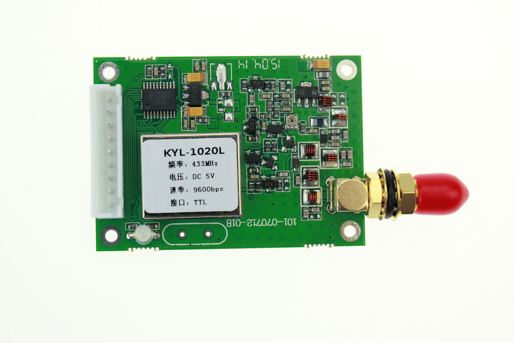
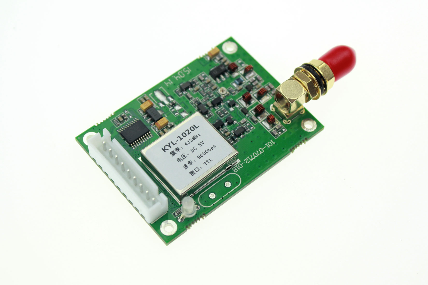
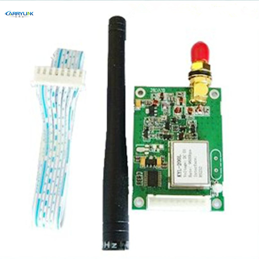
KYL-200L

1、Frequency Band: 433MHz, 450MHz,470MHz,868MHz,915MHz etc ISM Frequency Band;
2、8 channels, if needed, 16/32/64 channels are available to satisfy various configuration of communication at the same time;
3、Baud Rate:1200、2400、4800、9600、19200、38400bps;
4、Data format:8N1/8E1/8O1(Other formats can also be provided, such as 9-bit data bits to meet the requirements of multi-machine communication);
5、Interface:RS232/RS485/TTL;
6、Transparent data transmission,transparent data interface used in transceivers is for meeting many standard or nonstandard user protocols. Any false data generated in air can be filtrated automatically (What has been received is exactly what has been transmitted);
7、 Industrial-grade design, uses high-quality devices and high-precision Temperature compensation crystals to meet the needs of all-weather work. Reliable operating temperature up to -35°C to +80°C;
8、Big data buffer area, the transceiver can transmit unlimited data frames with flexible user program.the terminal can continuously send data to the module without buffer overflow and data loss;
9、Compatible with KYL series other modules with medium power (1W, 2W), high power (5W), convenient and flexible networking;
10、Complies with standard EN 300220 and ARIB STD-T67。
AMR Automatic Meter Reading;
Building automation, security, wireless monitoring and control of room equipment,Access Control System;
Wireless alarm and security systems, Wireless Queuing machine and Wireless medical containers;
Wireless POS, PDA wireless smart terminal ;
Wireless data transmission, automatic data collection system;
Wireless LED display, Responder and intelligent traffic;
Converting RS-485 cable to wireless communication, such as PLC。
| Features | Range | Remark |
| Power supply D.C. | 5v | 5-12v |
| Frequency | 433Mhz | 450-470Mhz |
| Output power | 500mW | -- |
| Transmitting Current | <300mA | -- |
| Receiving Current | <20mA | -- |
| Sleeping Current | <20uA | -- |
| Receiver sensitivity | -120dBm | 1200bps |
| -116dBm | 9600bps | |
| Transmission distance | 2-3Km | Line-of-sight, the height of antenna 1.5m |
| Dimension | 53mm×38mm×10mm | Without Antenna connector |
Baud rate(Bps) | Receiver sensitivity | Transmission distance |
1200 | -120dbm | 3000m |
2400 | -118dbm | 2500m |
4800 | -116dbm | 2000m |
9600 | -113dbm | 1600m |
19200 | -110dbm | 1000m |
1、When Module A transmits data and module B receives data
That is, the delay time that the terminal A (connected to the module A) sends data to the terminal B (connected to the B module) by wireless. Which be fixed to the time for transmitting 15 bytes. This time is related to the air baud rate, but not to the interface baud rate. details as follows:

Baud rate(Bps) | delay time(ms) |
19200 | 8 |
9600 | 15 |
4800 | 30 |
2400 | 60 |
1200 | 120 |
2、Module transceiver conversion time
That is, the time for converting from the receive state to the transmit state, or from the transmit state to the receive state. During this time (100us), the module cannot receive air data.

Power supply:
+3.3~6.0V DC. According to the needs of users, it can share the power with other devices, but please select a power supply with a better ripple factor.If conditional, 5V regulators can be used to supply power alone. It is recommended not to use the switching power supply. If you must use the switching power supply, please pay attention to the interference due to switching pulse.In addition, if there are other devices in the system equipment, it must be grounded reliably. Otherwise, it can be self-contained, but it must be completely separated from the city electricity. The maximum output current of the power supply should be more than 1.5 times the maximum operating current of the module.
Connection diagram for wireless module and computer: